- 您现在的位置:买卖IC网 > Sheet目录1222 > ISL6292EVAL2 (Intersil)EVALUATION BOARD 2 ISL6292
�� �
�
�Application� Note� 1064�
�TABLE� 2.� JUMPER� SETTINGS�
�ON�
�JUMPER�
�POSITION�
�USB� TO� VIN�
�FUNCTION�
�USB� input� selected�
�OFF�
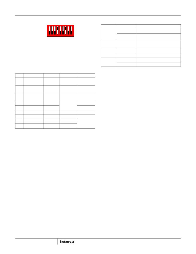
�123456789�
�JP1�
�WALL� CUBE� TO�
�VIN�
�Wall� adapter� input� selected�
�FIGURE� 1.� INITIAL� DIP� SWITCH� SETTINGS�
�DIP� Switch� Settings�
�A� 9-bit� DIP� switch� is� provided� to� set� up� voltage,� current� reference,�
�end-of-charge� (EOC)� current,� and� so� on.� The� functionality� of� the�
�bits� are� described� in� Table� 1.�
�JP2�
�JP3�
�JP4�
�Shunt� Installed�
�Shunt� installed�
�Not� installed�
�IREF� and� V2P8�
�IREF� and� GND�
�connect� VBAT� pin� to� battery�
�current� meter� can� replace� shunt�
�Battery� attached� to� Thermistor� at� J2�
�Default�
�Setting� USB� 500mA� mode�
�Setting� USB� 100mA� mode�
�TABLE� 1.� DIP� SWITCH� PIN� DESCRIPTIONS�
�Initial� Board� Jumper� Positioning� (Refer� to�
�BIT�
�1�
�2�
�3�
�4�
�5�
�6�
�7�
�8�
�9�
�DESCRIPTION�
�Adjustable�
�TIMEOUT�
�TIMEOUT�
�disable/enable�
�Charger�
�enable/disable�
�IREF� setting� 1�
�IREF� setting� 2�
�IMIN� setting�
�TEMP� normal�
�TEMP� high�
�TEMP� low�
�ON�
�5� hours�
�50� mins�
�TIMEOUT�
�disabled�
�charger�
�disabled�
�Add� 0.5A�
�Add� 1A�
�100mA�
�normal�
�too� hot�
�too� cold�
�OFF�
�3� hours�
�30� mins�
�TIMEOUT�
�enabled�
�charger�
�enabled�
�I� CHG� =� 0.5A�
�When� both� off�
�50mA�
�REMARK�
�All� off�
�simulates�
�battery�
�removal�
�Figure� 3)�
�JP1� -� Selects� the� VIN� pin� to� be� connected� to� either� a� wall�
�adapter,� or� to� a� USB� connector.� If� the� J1� connector� is� being� used,�
�a� shunt� must� be� installed� across� ‘WALL� CUBE� TO� VIN’,� or� if� the� J3�
�(USB)� connector� is� being� used,� a� shunt� must� be� installed� across�
�‘USB� TO� VIN’.� J1,� J3� and� JP1� can� be� ignored� if� the� power� supply� is�
�connected� directly� to� VIN� test� point,� which� is� directly� connected�
�to� VIN� pin� of� the� IC.� A� current� meter,� to� measure� the� input�
�current,� can� replace� the� shunt� mentioned� above.�
�JP2� -� Can� connect� the� VBAT� pin� to� the� battery.� If� the� J2� connector�
�is� being� used,� a� shunt� must� be� installed� across� JP2.� In� this� case,�
�a� current� meter� can� also� replace� the� shunt� to� measure� the� VBAT�
�current.�
�JP3� -� Can� connect� the� TEMP� pin� to� the� battery.� Usually� no� shunt�
�is� needed� for� JP3,� as� the� Evaluation� board� can� simulate� various�
�battery� thermal� conditions.� Only� when� a� battery� with� a� attached�
�thermistor� is� applied� on� J2� does� it� become� necessary� to� install� a�
�shunt� across� JP3,� simultaneously� turning� off� bits� 7,� 8,� and� 9� on�
�the� DIP� switch.�
�JP4� -� Selects� USB� modes;� a� shunt� across� IREF� and� V2P8� will� set�
�USB� 500mA� mode;� a� shunt� across� IREF� and� GND� will� set� USB�
�100mA� mode.� When� the� charge� current� is� programmed� by� the�
�resistors� connected� to� the� IREF� pin,� no� shunt� should� be� installed�
�on� JP4.�
�2�
�AN1064.1�
�July� 26,� 2011�
�发布紧急采购,3分钟左右您将得到回复。
相关PDF资料
ISL6296EVAL1
EVALUATION BOARD 1 ISL6296
ISL6298EVAL1
EVALUATION BOARD 1 ISL6298
ISL6298EVAL2
EVALUATION BOARD 2 ISL6298
ISL6299AEVAL1
EVALUATION BOARD 1 ISL6299A
ISL6411EVAL1
EVALUATION BOARD ISL6411
ISL6413EVAL1
EVALUATION BOARD ISL6413
ISL6420EVAL3
EVALUATION BOARD 3 ISL6420
ISL6521EVAL1
EVALUATION BOARD 1 ISL6521
相关代理商/技术参数
ISL6292EVAL2Z
功能描述:EVALUATION BOARD FOR ISL6292 RoHS:是 类别:编程器,开发系统 >> 评估演示板和套件 系列:- 标准包装:1 系列:PCI Express® (PCIe) 主要目的:接口,收发器,PCI Express 嵌入式:- 已用 IC / 零件:DS80PCI800 主要属性:- 次要属性:- 已供物品:板
ISL6293
制造商:INTERSIL 制造商全称:Intersil Corporation 功能描述:Li-ion/Li Polymer Battery Charger Accepting Two Power Sources
ISL6293_06
制造商:INTERSIL 制造商全称:Intersil Corporation 功能描述:Li-ion/Li Polymer Battery Charger Accepting Two Power Sources
ISL6293-1CR
制造商:Intersil Corporation 功能描述:SINGLE CELL LI-ION/POLYMER CHARGER, 10LD DFN 3X3 - Rail/Tube
ISL6293-1CR-T
制造商:Intersil Corporation 功能描述:SINGLE CELL LI-ION/POLYMER CHARGER, 10LD DFN 3X3, T&R - Tape and Reel
ISL6293-1CRZ
制造商:Intersil Corporation 功能描述:LEAD-FREE VERSION OF ISL6293-1CR - Bulk
ISL6293-1CRZ-T
制造商:Intersil Corporation 功能描述:LEAD-FREE VERSION OF ISL6293-1CR - Tape and Reel
ISL6293-2CR
功能描述:IC BATT CHRGR LI-ION 10-DFN RoHS:否 类别:集成电路 (IC) >> PMIC - 电池管理 系列:- 标准包装:1 系列:- 功能:充电管理 电池化学:锂离子(Li-Ion)、锂聚合物(Li-Pol) 电源电压:3.75 V ~ 6 V 工作温度:-40°C ~ 85°C 安装类型:表面贴装 封装/外壳:SC-74A,SOT-753 供应商设备封装:SOT-23-5 包装:剪切带 (CT) 产品目录页面:669 (CN2011-ZH PDF) 其它名称:MCP73831T-2ACI/OTCT